
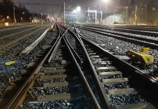
- Development of turnout structure
- Investigation of track errors in Hanala
- Monitoring of the double slips in Alppila
- The effect of rail side wear on train derailment risk and the convenience of train passengers
- Best tamping practices in turnout areas
- Rail vehicle model verification
- Rolling stock speed increase measurements and embankment vibration in Ylivieska-Liminka track
- Rail side wear and distance between flange contact faces of the wheelset
- Rolling stock−track interaction
- Detachment of snow from the rolling stock at rail discontinuities
- Statistical analysis of wheel impact load detector data
- Review of basic factors of rolling stock-track interaction
- Loads applied to track from vehicle-track interaction
- Railway rail rolling contact fatigue on Finnish rail network
- Eddy current inspection in railway rail monitoring
- Rail life cycle
- Monitoring the new elastic prototype turnouts
- Effectivity of under sleeper pads in turnouts
- Functionality of the new spring device
- Preliminary report on switch inspection wagons and devices
- Complications of vertical stiffness of railway turnout and its countermeasures
- Detection failures in signaling system caused by train passages
- Rolling stock-induced lateral vibration in a railway switch
- Opening mechanism of Railex
Development of turnout structure
Over the years, several different problems related to turnouts safety, stiffness and actuation have been identified in the turnout structures of the Finnish state rail network and different kinds of solutions for those have been sought. In cooperation with turnout suppliers, new elastic turnouts have been developed and introduced few years ago, which seek to correct several identified problems. Experience with new elastic turnouts has been mainly good, although numerous problems have also emerged. In addition, the development of rail traffic is creating pressure to increase axle weights and speeds in turnouts.
Based on these identified problems and actions taken, the main objective of this study is to identify which issues would be most critically affected by the potential higher speed and axle weight of new elastic turnouts and which issues should be considered in the design if speeds are increased to 250 km/h. Alongside the development of high-speed turnouts, the long time period effects of under sleeper pads on the stability of track geometry and the benefits of rail lubrication to reduce rail side wear and noise in the diverging route are also investigated. In addition, the report reviews how maintenance values for existing point machines should be developed to reduce false openings of point machines.
The work includes a literature review of the special features of high-speed turnouts structures, component solutions used in other countries, and current legislation, regulations and guidelines in Finland and in EU. In addition, the work determines computationally how much loads the different structural layers of the turnout would be subjected to at these designed high speeds. The effects of under sleeper pads on the stability of track geometry and the effects of lubrication on rail wear and noise have been determined by field measurements on the Ring Rail Line and in Oulu.
The literature review and the calculations show that the current elastic turnout structure in Finland would withstand loads caused by even higher speeds, as long as a movable crossing is used, which reduces the dynamic impact loads in the crossing area. In addition, high-speed turnouts should always be built far enough away from each other so that they can be tamped and maintained individually.
The results related to under sleeper pads obtained from Ring Rail Line reveals that turnouts equipped be USP retain their geometry in long period slightly better than non-USP turnouts. For this reason, it is important to pay special attention to the very first tamping procedure, because the good geometry achieved there is maintained with the USP-sleepers for a very long time.
More information: Doctoral researcher Riku Varis
Investigation of track errors in Hanala
The main goal of this study was to find out, why the track junction in Hanala has major geometrical errors, which causes train delays even though there are continuous maintenance efforts. After those reasons for errors has been clarified, the aim is to give recommendations how to fix those problems, so that the stability of track would be better in future.
In this study the track inspection history and the development of errors has been examined. During the study, geometrical measurements were done 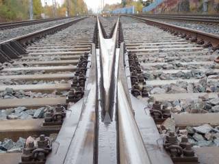 with the help of GEDO track survey trolley, reversible deflection of track was measured as well as cross-section profiles of crossings. Also the condition of ballast and substructure was inspected with the help of soil samples from every turnout area. One of the track inspection measurement was done only two days after tamping the whole area and the results of inspection showed that this tamping couldn’t remove all the short wavelength elevation errors, which has developed around crossing nose. Also cant and twist errors remained throughout the tamping.
The current tamping methods in Finland are not the ideal ways to remove short wave-length errors. The main reason for that is too short chord system. The measurement chords are created in this area only once in 10 meters and none of these points were actually in the crossing nose area. That is the reason why the lift of the crossing area was insufficient during tamping. Another critical reason for the immediate errors could be that the plotter of tamping machine doesn’t print the elevation at all. This could mean that tamping machine actually doesn’t even try to correct the short wavelength errors in reference rail. The cant errors are at least corrected automatically, which can be seen at the results where lift values of another rail change often than reference rail.
The long turnout bearers are often little bit convex. This leads to situation where there is always some kind of cant values either on straight route or diverging route. This feature is probably not commonly known among the tamping crew. During the tamping process the straight route is commonly tamped first and the attempt is to remove all the cant in this route. After that the diverging route is tamped and the aim is same, which turns the straight route and leaves crossing nose higher that straight route reference rail. So when the bearers are convex, the tamping of the diverging route could easily weaken the tamping results of straight route. These problems are even in-creased if there are adjustment plates underneath the crossing as in Hanala. These adjustment plates also increase the stresses in the overall structure leading to straightening of these convex bearers through bending or creeping in long term.
The soil samples reveal that the structural layers of track are appropriate, even thought the thickness and properties of different layers varied a little bit. The granularity of ballast was almost as new and the middle layer was good and frost insulation was done by frost insulation plates. Underneath the frost insulation plates there are old crushed ballast or middle layer material approximately 0,3 m. Underneath these materials are insulating sand, which is little bit finer than instructed. All the materials were actually little it finer than instructed. The overall thickness of structure is approximately 1,4 – 1,6 meters, which can be said to be adequate to the loads in Hanala. Soil samples from the middle layer above the frost insulation plate and the old crushed ballast under-neath the plate was completely wet. It seems like the frost insulation plate is disturbing the drainage of above layer and old ballast contains so much fines that it binds water.
More information: Doctoral researchers Riku Varis & Tommi Rantala, Project manager Heikki Luomala
Monitoring of the double slips in Alppila
The goal of this study was to monitor the condition and the stresses and movements of four diamond crossings with double-slip V460-V463 located in the Helsinki. The research period of this study was 07/2020 – 12/2020. These double slips have been caused excessive amount of maintenance work before the monitoring period, so the reasons for these problems had to be clarified.
 This research concentrates to condition and the maintenance history of these turnouts and also reveals the distinguished main problems. Several obtuse crossing noses have been welded and totally replaced during recent years. Despite these repeated maintenance actions, several surface defects were noticed in the inspections on spring 2020 and finally two separate obtuse crossings cracked.
The research also presents the recent results of Finnish track inspection car EMMA. These results reveal that many class D rail errors have been measured in these turnouts during recent years, especially in turnout V460, which has the worst condition. Tamping process in spring 2020 has removed many of these class D errors and deterioration of track geometry has been really slow after that. Unfortunately, this tamping excluded the turnout V460, which is still in bad geometrical condition.
The research report shows the measurement arrangements along with results and analysis from those measurements. The measurements showed that the vertical reversible deflections of bearers are moderate, which means that the tamping has been quite successful under these obtuse crossings. The reversible deflection was 1-3 mm, which is little bit more than in normal main line. Still, this kind of deflection cannot be the main reason for the cracked crossings in the turnouts V461 and V463. Visual inspections also assured that the surface defects haven’t been increased between the first inspection on August and the second inspection on November.
The effect of the reversible deflection on the rail stresses was measured from the obtuse crossing and results showed that the strain of crossing was close to normal strains in the main line. This means that the actual loads in the crossing are much bigger, because the structure of obtuse crossing is more rigid than in main line. The final strain is highly dependent on the rail surface defects, which increases the dynamic factor of train loads. Nevertheless, it was discovered that the strain doesn’t increase with the train speed. During this inspection period, the maximum operation speed in this area was decreased to 30 km/h – 60 km/h, so it was not possible to study the relationship between strain and train speed on the maximum obtuse crossing operation speed, which is 80 km/h in Finland.
Overall, the geometry of these monitored double slips has remained quite well during this study. The main reason for that is the 60 km/h speed limitation set in May 2020. After this modification the rail wear is still detectable, but the degradation of rails is dramatically slower. With these results it is recommendable to keep this speed limitation valid also for the future. If there is a necessary need to increase the operation speed back to normal 80 km/h design level, this kind of monitoring should be done again to assure that the relationship between rail strain and train speed remains controlled.
More information: Doctoral researcher Riku Varis
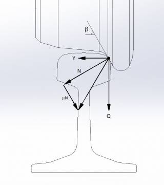
The effect of rail side wear on train derailment risk and the convenience of train passengers
Increasing rail side wear limits would decrease the need for rail change and rail grinding which would bring on great financial benefits. Side wear in rail,
however, changes track gauge and rail profile shape, which immediately affects train movement. It is typical that in curves rail wear occurs on the side of rail head and in straight track on top of rail. As a phenomenon, rail side wear is more severe than rail top wear since strong rotational creep forces will arise in the contact between wheel flange and rail side.
 The aim of this project was to observe the validity of current rail side wear limits in Finland. It was also important to look at potential derailment risk caused by strong rail side wear, especially in good quality track sections with high velocities. The project also included evaluation of train passenger inconvenience and its dependency on rail side wear. Literature review was made to find out how rail side wear limits in Finland compare to other countries. It was found out, that the limits in Finland are quite strict.
In calculational study, rail side wear was consistently noticed to weaken wheelset guiding properties, which increases the amount of wheelset side movement in curves. However, due to rail side wear, track clearance has also grown, so there is more space for the wheelset to move laterally without flange contact. Flange contact always causes a high lateral force, which increases the value of Y/Q and therefore the risk of derailment.
 Based on simulation results, it was concluded that rail side wear limits in Finland can be increased several millimeters. Rail side wear was not noticed to cause any significant change on train derailment risk or passenger inconvenience. Train guidance properties are mainly affected by the shape of rail profile, not the amount of rail side wear.
Unstable behavior of a vehicle is one obvious reason for higher derailment risk. In a large number of simulations made in this project, unstable behavior was observed a few times. Reason for that, however, was not the amount of side wear in rail directly, but rather the poor interoperability in the combinations of rail and wheel profiles.
Rail side wear limits in Finland can be increased, but it requires some control measurements to be done in both vehicles and track, to be sure that the Y/Q value stays low enough. Along with rail wear, the rate of rail wear may also rise, and it is good to be prepared for that. This phenomenon, however, is highly dependent on the combinations of wheel and rail profiles. Therefore, the rate of rail wear varies in different track sections.
More information: Doctoral researcher Tiia Loponen