
The construction of our compression test equipment is shown schematically in the figure below. The SHPB device consists of a striker and incident and transmitted pressure bars. The typically cylindrical specimen is placed between the incident and transmitted bars. A third bar, called the momentum trap bar, can also be added after the transmitted bar to trap the residual transmitted pulse and to prevent it from reflecting back to the transmitted bar as a wave of tension. The test is performed by impacting the striker bar on the free end of the incident bar and thus producing a compressive stress pulse into it. This pulse travels towards the specimen and when it reaches the interface between the bar and the specimen, part of the wave is transmitted to the transmitted bar while part of it is reflected back into the incident bar as a wave of tension. The specimen undergoes a dynamic elasto-plastic deformation as the stress pulse travels through it. The three stress pulses, incident, reflected, and transmitted, are measured from the pressure bars using one or more strain gages, which are bonded on the surfaces of the bars. The signals are amplified and recorded using a high accuracy high speed measurement system, i.e., a high-bandwidth strain gage amplifier and a fast digital oscilloscope. The stress, strain, and strain rate in the material can be calculated from the recorded pulses with a time resolution of 1 μs or better.
The SHPB method is a highly specialized research tool, the designing, building, and utilization of which requires versatile understanding of the propagation of elastic waves in solids, modern machine design, and instrumentation of electronic measurement devices and data acquisition systems. At TAU, there are three HSB devices, two for compression and one for tensile testing. The compression apparatuses built at TAU use high strength 4340 steel (yield strength ~ 1100 MPa), maraging steel (yield strength ~ 1900 MPa), and 7075 aluminum alloy (yield strength ~ 520 MPa) bars. The tensile apparatus uses 4340 steel incident bars and 2007 aluminum alloy transmitted bars. Each bar is supported by three bearings at four or more stanchions, which can be individually translated in y and z directions to assure precise alignment of the bars. The diameter of the bars is either 22 or 12 mm, and their length varies from 1200 to 2400 mm in the compression systems, and from 3000 mm to 4500 mm in the tensile system. The striker bar’s length, affecting the loading pulse duration, varies from 100 to 1500 mm in the compression system and from 500 to 800 mm in the tension system.
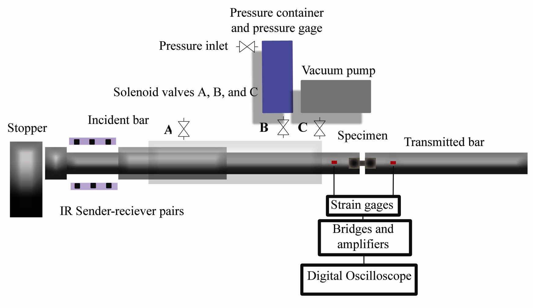
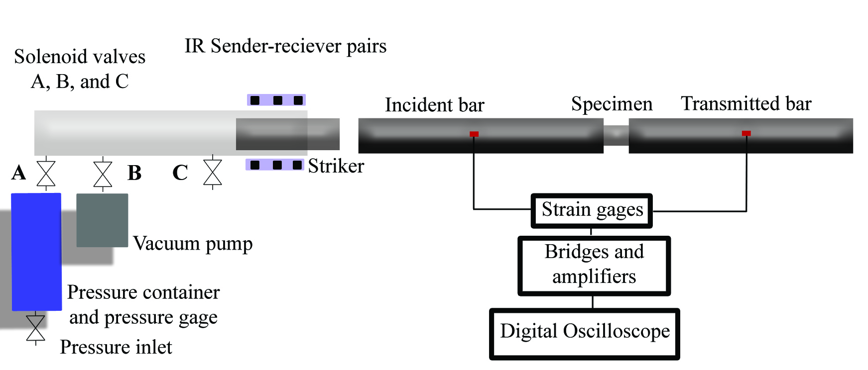
The velocity of the striker bar (or striker tube in the tensile SHPB system) is computed from signals given by optical sensors mounted at the end of the launcher tube at equal distances from each other. The signals from the optical sensors and strain gages are recorded using a 12-bit 10 MHz Yokogawa digital oscilloscope. The strain gage signals are amplified using Kyowa CDV 700A series signal conditioners having a bandwidth of 500 kHz. The compression HSB device is also equipped with a high/low temperature system, which allows experiments in the temperature range of -190 °C to 1000 °C, and a recovery (stress reversal) system, which allows only the first incident pulse to deform the specimen.
The stress, strain, and strain rate in the specimen are calculated from the elastic stress pulses in the bars using a Matlab code. The dispersion of stress waves in the pressure bars is corrected using the Bancroft correction method and the Fast Fourier Transform. From the corrected pulses the stress, strain, and strain rate data can be calculated according to the theory of elastic wave propagation in cylindrical bars.
High temperature system
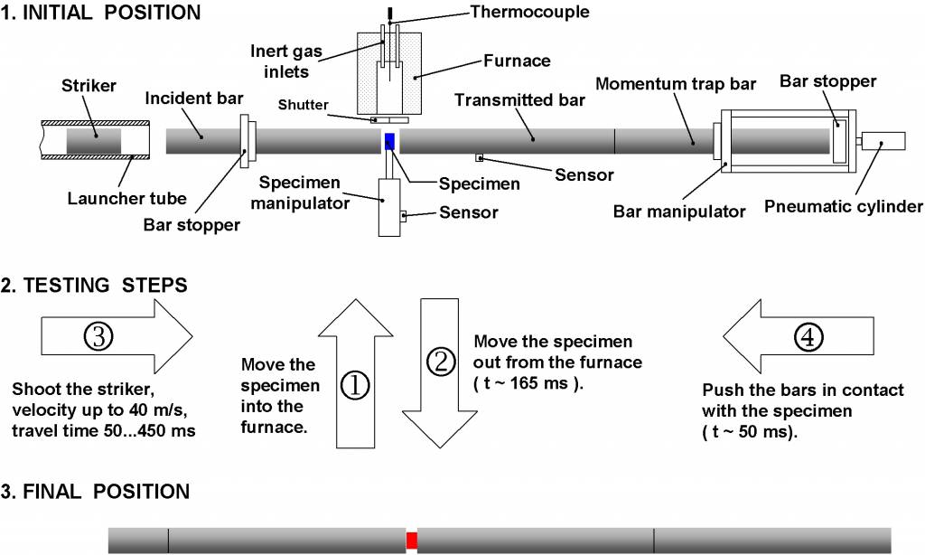
The figure below shows a schematic picture of the construction and operation of the high temperature system that has been developed at TAU. In order to avoid heating of the bars, the furnace is placed beside the bars and the tests can be carried out by mechanically manipulating the specimen and the bars. The specimen is fixed in a ceramic wool ring, which is placed in a special specimen holder arm, which can be pneumatically moved back and forth from the centerline of the bars to the furnace. The test starts by first moving the specimen into the hot furnace, which is a small tube furnace located beside the bars. The specimen is kept at the test temperature for about 5-10 minutes to ensure homogenous temperature within the specimen. Secondly, the specimen is rapidly pulled to the centerline of the bars, and the striker bar is shot. The specimen and the bars are then pushed into contact by a second mechanical manipulator at the end of the momentum trap bar just a fraction of a second before the impact of the striker bar and the incident bar. This system limits the contact time between the hot specimen and the cold bars to about 50 ms, during which the surface of the specimen does not cool down too much.
HIGH TEMPERATURE TENSION SYSTEMS
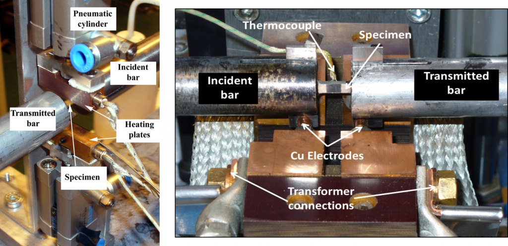
High temperature tension testing is complicated because of the need to fix the sample to the stress bars. Therefore, you cannot manipulate the sample and the bars after the sample has been fixed to the bars. There are many different approaches to high temperature testing, and most of them use mechanical fixing of the sample to the bars. Our solution is to glue the sample to the bars and heat the specimen to the test temperature very quickly before the test. This has the benefit that there are no extra material and interfaces in the sample-bar fixtures. This reduces the unwanted oscillations and noise in the measured force signals, and therefore, gives better quality results. The down side of course is that the test itself is more complicated and carrying out one test takes more time. We have developed two high temperature test systems for the tension device. The first one (Figure below left) uses two hot copper blocks to heat specimen. In the begining of the test, the copper blocks are pushed against the small specimen, and the temperature of the sample quickly rises to the test temperature. The heating of the sample takes approximately 10-15 seconds. After this, the striker is fired, the copper blocks are retracted from the specimen, and the test carried out on the heated specimen. This method, however, has a temperature limit of approximately 250 centigrade. For higher temperatures, we use the second test system shown on the right hand side in the figure below. In this method we drive DC electric current through the sample. This heats the sample in less than a second up to the melting point of the specimen. The test is carried out by first shooting the striker bar, then heating the specimen, and releasing the electrodes from the specimen just fraction of a second before the impact. This allows testing of the specimen at very high temperatures, but lacks proper control of the temperature. Even though we measure the test temperature and know it exactly after the test, it is difficult to preset the test very accurately prior to the test. Because of this the tests are typically carried out in a certain temperature range instead of exact temperature. For example, one can carry out 5 tests at temperatures ranging from 550 to 650 centigrade, but most likely the temperature in each test will be slightly different.
LOW TEMPERATURE SYSTEM
The same specimen and bar manipulation systems are also used for the low temperature system, but the furnace is replaced by a cooling chamber where the specimen is cooled to the test temperature. The low temperature test system uses cryogenic nitrogen gas to cool down the specimen. The nitrogen gas is flowed through a heat exchanger, which is immersed in liquid nitrogen, to the cooling chamber. The temperature of the specimen is controlled by adjusting the flow rate of the nitrogen gas into the heat exchanger by a PID controlled piezoelectric proportional valve. This system enables precise control of the temperature with an accuracy of ±0.5 K of the thermocouple reading. The achievable temperature range is from room temperature to about -150 °C. The low temperature test procedure is otherwise exactly the same as for the high temperature tests.