Y. Lu*, M. Koivisto*, J. Talvitie*, E. Rastorgueva-Foi*, M. Valkama*, and E. S. Lohan*
* Department of Electrical Engineering, Tampere University, Finland
The millimeter wave (mmWave) device-to-device air interface not only supports a direct wireless connectivity, but it also enables the beamforming capability to obtain the direction information among the vehicles and devices for positioning. Both features serve as the key physical layer components for communications and positioning in the industrial Internet of things (IIoT) systems. Exploiting both beamforming and wide bandwidth in a mmWave network, high-accuracy positioning is achievable, which can be then facilitated for location-aware communications, for instance. However, the uncertainty of anchors’ locations in the industrial environment highly degrades the achievable positioning accuracy if left without proper consideration. In order to resolve such challenge, this paper presents a cooperative positioning system (CPS), where the locations of all the vehicles and anchors can be jointly estimated based on acquired location-related measurements (LRMs). Furthermore, the positioning performance is evaluated under random trajectories and different geometric relationships between the vehicles and the anchors. We show that, the proposed positioning solution is capable of resolving the aforementioned challenge by simultaneously tracking the mobile vehicles while mapping the locations of the static anchors. Utilizing the LRMs from both time and angular domains, the achieved positioning accuracy in both 2D and vertical plane is demonstrated based on extensive numerical simulations. Last but not least, the impact of different numbers of the mobile vehicles on the overall positioning performance is also investigated.
Accepted for publication in IEEE 93rd Vehicular Technology Conference (VTC2021-Spring).
Videos and Demonstrations
The two plots on the left illustrate the positioning performance of a multi-target CPS (MT-CPS) (top plot -> 2D, bottom plot -> vertical) where there are two target-agents (T-ags) (cyan star and diamond markers) being involved, whereas the two plots on the right are the positioning performance of a single-target CPS (ST-CPS) where only one T-ag (cyan diamond marker) is considered. In both systems, we consider overall six anchor-agents (A-ags) which are collinear and non-collinear deployed. In addition, we assume that they are located on the same height, and illustrated with the red circle markers. Furthermore, the blue diamond and magenta star markers (on the left plots) are the estimated locations of the two T-ags with the proposed MT-CPS, while the red diamond marker (in the right plots) refers to the location estimates of the only T-ag with the ST-CPS. In both cases, the green ellipses are indicating the 95% uncertainty in the obtained location estimate. Additionally, the cross markers therein represent the estimated locations of the A-ags (solid lines with different colors are applied to connect the estimates with the corresponding A-ags in 2D plots).
Last but not least, the plots in the middle refer to the cumulative density function (CDF) of the positioning error on the 2D plane and vertical direction, in which, black curves are showing the estimation performance of the MT-CPS (solid for T-ags and dashed for A-ags), whereas the red ones are showing the estimation performance of ST-CPS (solid for T-ags and dashed for A-ags). We emphasize that the results presented in the videos applies for this specific realization only, and therefore, the performance cannot be directly generalized.
Parameters utilized in the simulation: The OFDM-based pilot signal is transmitted at 26 GHz with 10 MHz bandwidth (60 kHz sub-carrier spacing) and 10 dBm transmit power. Meanwhile, an 8 x 8 URA is assumed for each A-ag. The update time-interval is set at 100ms.
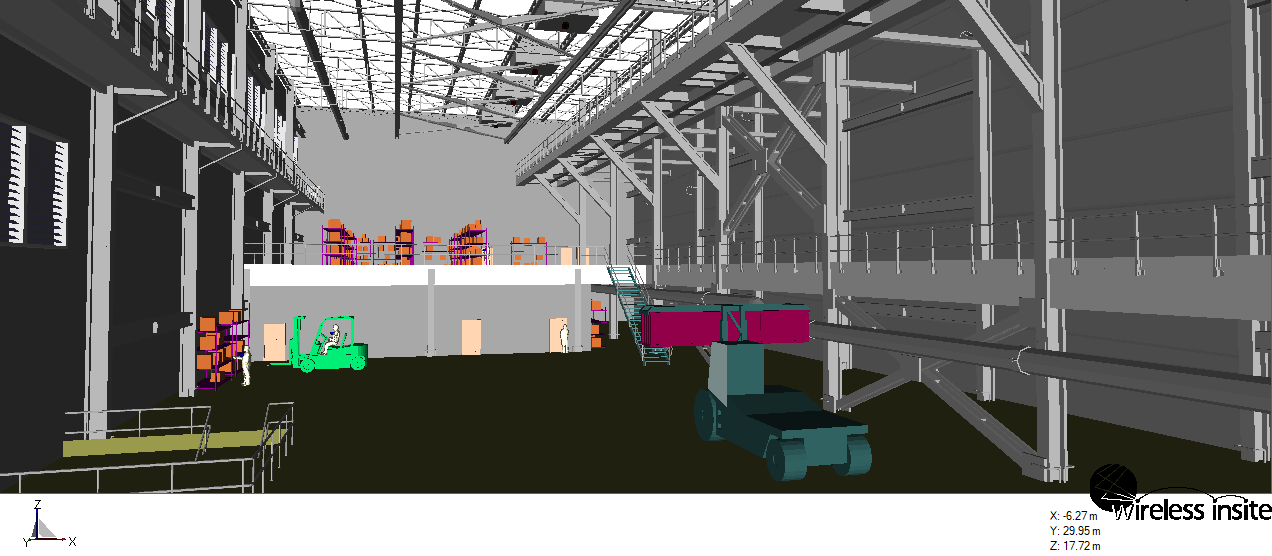
The location-related measurements (LRMs) utilized in the positioning are time of arrival (ToA), angle of arrival (AoA) and time difference of arrival + angle of arrival (TDoA+AoA), and they are shown in the titles of both 2D plots. The path information utilized for characterizing the LRMs are generated in the following environment (with a few modifications) using Wireless Insite, Remcom Incooperation (https://www.remcom.com/wireless-insite-em-propagation-software).